Tag-Archive for ◊ Arduino ◊

30 Nov 2013 Physical Android Notifier
 |  Category: Electronics  | Tags: ,  | 7 Comments

I wanted to create a simple notifier for my Android phone. Something that would blink whenever I have a missed call, or sms or whatsapp notification.

The hardware part was easy:

  1. Funduino Mini Pro
  2. Common Anode RGB LED
  3. Switch
  4. Bluetooth Breakout Board

more…

13 Nov 2013 Digital Pin-Art – WIP
 |  Category: Electronics  | Tags: , , ,  | One Comment

I’m planning to create a digital “pin-art” board – something similar to the photo below.

Source: http://cdn.visualnews.com/wp-content/uploads/2011/05/Lulu-Guinness-11.jpg

more…

11 Nov 2013 Standalone Temperature and Humidity Control
 |  Category: Electronics  | Tags: ,  | 7 Comments

Continuing from Standalone Arduino and Thermometer and Humidity Control, created a standalone thermometer and humidity control. Added the following features:

  1. Added a push-button to allow controlling the setpoint temperature
  2. Used the EEPROM library to save the setpoint temperature
  3. Enclosed everything in an extension cord with a power supply
  4. Left a socket to update programming as required

more…

26 Oct 2013 Charlieplexed LEDs with Arduino (Induino)
 |  Category: Electronics  | Tags: ,  | Leave a Comment

Using ideas from:

more…

14 Oct 2013 Standalone Arduino
 |  Category: Electronics  | Tags:  | 7 Comments

Now that the circuit for my Temperature and Humidity Control is working – its time to create a standalone micro-controller circuit so that I can free up my Induino.

References:

http://arduino.cc/en/Tutorial/ArduinoToBreadboard

http://arduino.cc/en/Hacking/PinMapping168

http://www.instructables.com/id/The-RRRRRRRRRRBA-or-What-They-Dont-Teach-You-in-/step5/Some-Caveats/

Shopping List:

  1. Atmega 328P-PU (without bootloader)
  2. 16 MHz Crystal
  3. 2 x 22 pf capacitors
  4. LM 7805
  5. 1 uF + 10uF Electrolytic capacitors
  6. 10k Resistor
  7. General purpose PCB

All-in ~250 bucks. Had a 9V 1A power supply at home – so that was free. Needed a 9V for the relays that I had – otherwise you can use a 5V USB adapter that comes with most mobiles and gadgets. I have 8-10 lying at home 🙂

Wiring the Components:

Wire up the components as per the diagram below:

Arduino Standalone_bb

Burning the Bootloader:

  1. Connect your arduino to your computer using the USB cable.
  2. Select your board type and port from the Tools Menu
  3. Open the Arduino ISP sketch from examples
  4. Upload to your Arduino (clone)
  5. For the Induino – you can modify the LED numbers as follows: Lines 49-51 in the code. LED_HB 13; LED_ERR 12; LED_PMODE 11; Edit: Just realised – pins 11, 12, 13 are used for actual programming and should not have LEDs attached to them.
  6. This would allow you to use the in-built LEDs to show the bootloading process (purely optional)
  7. Select Tools->Board->Arduino Uno (the sources say use either Nano or Duemilanove – but Uno works just fine; I selected Uno so that I don’t have to keep changing the board every time I program my standalone kit)
  8. Select Tools->Programmer->Arduino as ISP
  9. Select Tools->Burn Bootloader
  10. Congrats – you have a working standalone arduino (albeit with some limitations)

You can disconnect the cables from your Arduino to the standalone board

 Uploading Sketches

Since our clone doesn’t have a USB-TTL interface, we have to use our arduino to program it. (this is one of the limitations :-))

  1. Remove the micro-controller from your Arduino (I’m trying to skip this step – so if anyone knows a better way – I’m all ears)
  2. Connect Rx pin to Pin 2 on the micro-controller
  3. Connect Tx pin to Pin 3 on the micro-controller
  4. Connect RST pin to Pin 1 on the micro-controller
  5. Connect power to the board (either through arduino or separate)
  6. Connect your arduino to the computer
  7. Upload sketch as usual


14 Oct 2013 Thermometer and Humidity Control
 |  Category: Electronics  | Tags:  | 2 Comments

The first thing that came to my mind when I started microcontroller programming was to set an automatic room heating cum humidifier system.

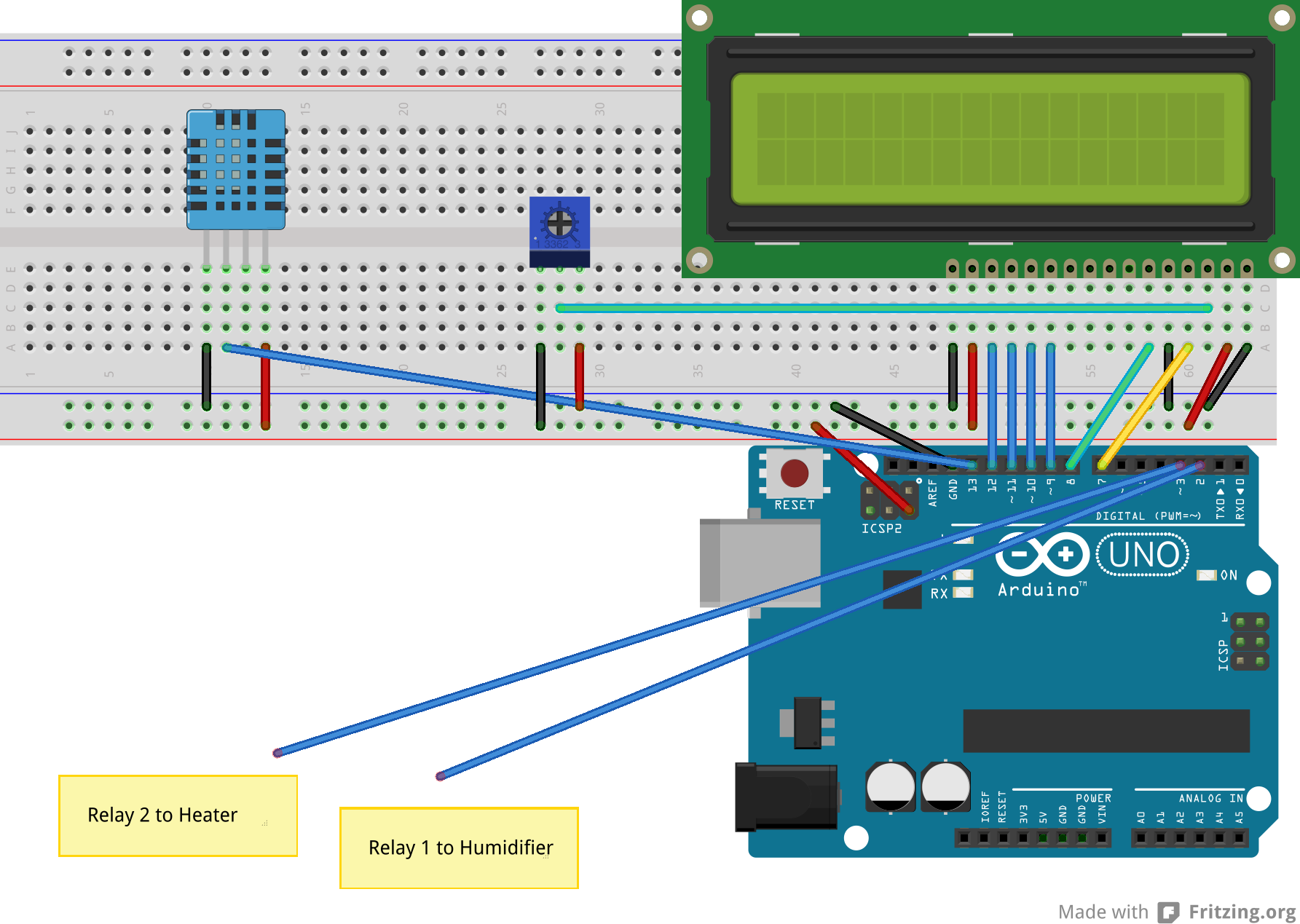
First off – bought a DHT11 sensor module. Then went about setting up the circuit. Added the LCD to boot – to show the temperature and humidity.

Set up the circuit as follows:

Thermometer_bb

Code as follows:

#include 
#include 
#define DHT11PIN 13
#define RELAY1 2 // Connect humidifier to Relay1
#define RELAY2 3 // Connect heater to Relay2
#define TEMP_SET 20.0
#define HUM_SET 35.0

dht11 DHT11;
LiquidCrystal lcd(7, 8, 9, 10, 11, 12);

void setup() {
  lcd.begin(16, 2);
  pinMode(DHT11PIN, INPUT);
  pinMode(RELAY1, OUTPUT);
  pinMode(RELAY2, OUTPUT);
}

void loop() {
  // put your main code here, to run repeatedly: 
  int chk = DHT11.read(DHT11PIN);
  // Serial.print("Read sensor: ");
  switch (chk)
  {
    case DHTLIB_OK: 
               // Serial.println("OK"); 
                break;
    case DHTLIB_ERROR_CHECKSUM: 
               // Serial.println("Checksum error"); 
                break;
    case DHTLIB_ERROR_TIMEOUT: 
               // Serial.println("Time out error"); 
                break;
    default: 
                lcd.println("Unknown error"); 
                break;
  }
  lcd.setCursor(0, 0);
  lcd.print("Humidity: ");
  lcd.print((float)DHT11.humidity, 2);
  lcd.setCursor(0, 1);
  lcd.print("Temp: ");
  lcd.print((float)DHT11.temperature, 2);
  if(DHT11.humidity < 50){ 
    digitalWrite(RELAY1, HIGH);
    lcd.print("H1");
  }
  else {
    digitalWrite(RELAY1,LOW);
    // lcd.print("H0");
  }
  if(DHT11.temperature < 25){ 
    digitalWrite(RELAY2, HIGH);
    // lcd.print("T1");
  }
  else {
  digitalWrite(RELAY2,LOW);
  lcd.print("T0");
  }
  delay(900000);
}

Worked like a charm – next steps:

  1. Add two buttons to change the temperature presets – save preset in EEPROM
  2. Create a standalone arduino so that I don’t have to give up my Induino for this small project