Craziest Batch to Join MBEM (SPA)
Had made this comic just after we graduated from the School of Planning and Architecture. Found it …
Had made this comic just after we graduated from the School of Planning and Architecture. Found it …
I finally sat down to code my own theme –
Wrote the entire thing from scratch (except the comments …
Have been ignoring my blog for quite some time now, so decided to make a to-do list of things yet to …
EDIT: Found a much easier and better recipe at Epicurious:
I had an old Dell Inspiron 6400 lying around at home and decided to install Linux on it – had been …
Yours truly has entered the publishing domain – first (and probably last article) published in a …
Apologies for the bad quality of the photographs – used my blackberry as I was too lazy to get out …
Finally bought a car:
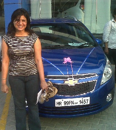
For those who don’t know the full story:
Hundreds of people buy cars every day in India – who would have thought that the process was so …
Another yummy dish I prepared – got the basic recipe from the net – modified to suit “Indian …
Yay!!,
Madhur, my sister, and Aossum, her venture, are in the news.
Just came across the essays I had put in for my ISB applications. Thought I’d share them here:
The …
Photos I’ve taken along the years:
I was given the opportunity by my company to speak at this year’s RENEWTECH in Pune.
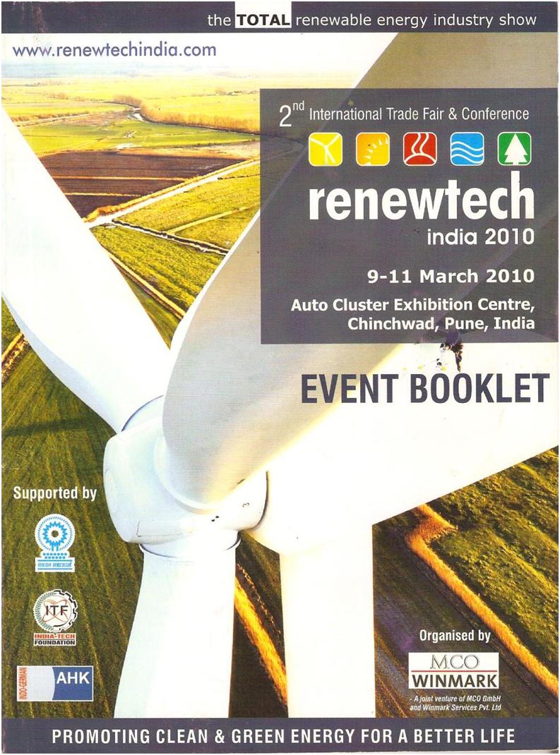

It was an …