Thermometer and Humidity Control

The first thing that came to my mind when I started microcontroller programming was to set an automatic room heating cum humidifier system.

First off – bought a DHT11 sensor module. Then went about setting up the circuit. Added the LCD to boot – to show the temperature and humidity.

Set up the circuit as follows:

Thermometer_bb

Code as follows:

#include 
#include 
#define DHT11PIN 13
#define RELAY1 2 // Connect humidifier to Relay1
#define RELAY2 3 // Connect heater to Relay2
#define TEMP_SET 20.0
#define HUM_SET 35.0

dht11 DHT11;
LiquidCrystal lcd(7, 8, 9, 10, 11, 12);

void setup() {
  lcd.begin(16, 2);
  pinMode(DHT11PIN, INPUT);
  pinMode(RELAY1, OUTPUT);
  pinMode(RELAY2, OUTPUT);
}

void loop() {
  // put your main code here, to run repeatedly: 
  int chk = DHT11.read(DHT11PIN);
  // Serial.print("Read sensor: ");
  switch (chk)
  {
    case DHTLIB_OK: 
               // Serial.println("OK"); 
                break;
    case DHTLIB_ERROR_CHECKSUM: 
               // Serial.println("Checksum error"); 
                break;
    case DHTLIB_ERROR_TIMEOUT: 
               // Serial.println("Time out error"); 
                break;
    default: 
                lcd.println("Unknown error"); 
                break;
  }
  lcd.setCursor(0, 0);
  lcd.print("Humidity: ");
  lcd.print((float)DHT11.humidity, 2);
  lcd.setCursor(0, 1);
  lcd.print("Temp: ");
  lcd.print((float)DHT11.temperature, 2);
  if(DHT11.humidity < 50){ 
    digitalWrite(RELAY1, HIGH);
    lcd.print("H1");
  }
  else {
    digitalWrite(RELAY1,LOW);
    // lcd.print("H0");
  }
  if(DHT11.temperature < 25){ 
    digitalWrite(RELAY2, HIGH);
    // lcd.print("T1");
  }
  else {
  digitalWrite(RELAY2,LOW);
  lcd.print("T0");
  }
  delay(900000);
}

Worked like a charm – next steps:

  1. Add two buttons to change the temperature presets – save preset in EEPROM
  2. Create a standalone arduino so that I don’t have to give up my Induino for this small project


Mango Pi

Continuing my saga with electronics – went for an electronics workshop by Kits’n’Spares – the workshop was nothing to talk about – however did get me a Mango Pi – a development board for the PIC processors.

Well surprise – surprise – doesn’t support Mac OS, at least I couldn’t get it to work. Finally gave up, started Windows XP in parallels, downloaded the software and started programming. Its not as easy as the arduino, but fun nevertheless. Took me a whole day to program the LCD. The code samples provided with the kit didn’t work and had to troll through the net to understand how to make it work. Finally got it working, here’s the code:


/* 
 * File:   LCT Trial.c
 *
 * Created on October 6, 2013, 7:56 PM
 */

#include 
#include 
#include 
/*
 *
 */

// PIC16F877A Configuration Bit Settings

#include 

// #pragma config statements should precede project file includes.
// Use project enums instead of #define for ON and OFF.

// CONFIG
#pragma config FOSC = XT        // Oscillator Selection bits (XT oscillator)
#pragma config WDTE = OFF       // Watchdog Timer Enable bit (WDT disabled)
#pragma config PWRTE = OFF      // Power-up Timer Enable bit (PWRT disabled)
#pragma config BOREN = OFF      // Brown-out Reset Enable bit (BOR disabled)
#pragma config LVP = ON         // Low-Voltage (Single-Supply) In-Circuit Serial Programming Enable bit (RB3/PGM pin has PGM function; low-voltage programming enabled)
#pragma config CPD = OFF        // Data EEPROM Memory Code Protection bit (Data EEPROM code protection off)
#pragma config WRT = OFF        // Flash Program Memory Write Enable bits (Write protection off; all program memory may be written to by EECON control)
#pragma config CP = OFF         // Flash Program Memory Code Protection bit (Code protection off)

/*
 * 
 */
char name1[32]={"Lots of Love -- Dushyant        "};
int counter=0;

void delay(int x)
{
	 int d,l;
	for(l=0;l<x;l++)
 	{ 
	for(d=0;d<1000;d++);
	}
}

void instwrt(int x)
	{
    PORTC=0b00000100;
    PORTD=x;
    PORTC=0b00000000;
    delay(1);
    PORTC=0b00000100;
}

void datawrt(int x)
	{
    PORTC=0b00000101;
    PORTD=x;
    PORTC=0b00000001;
    delay(1);
    PORTC=0b00000101;
    counter++;
    if (counter==16){
        instwrt(0xC0);
    }
    if (counter==32){
        instwrt(0x80);
    }
	}
void lcdin()
	{
    delay(5);
    instwrt(0b00001111);
    instwrt(0b00111101);
    instwrt(0b00000010);
    instwrt(0b00000001);
	}

void main(void) {
    int a;
    TRISB = 0x00;
    PORTB = 0b00000010;
        TRISD=0x00;
	TRISC=0X00;
        //PORTC=0b00000010;
        // PORTD=
        lcdin();
        PORTB=0b010;
	for(a=0;a<32;a++)
	{
	   	datawrt(name1[a]);
                delay(5);
         //       PORTB=name1[a];
	}
while(1)
{
	instwrt(0x18);
	delay(50);
}
}

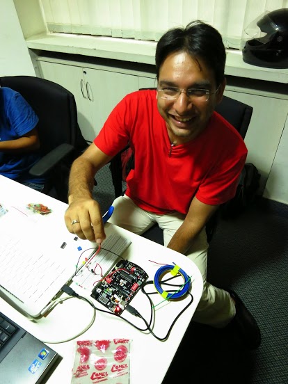
My First Arduino Circuit

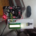
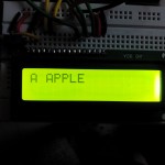
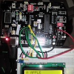
After the workshop, I plugged in my Indiuno with the LCD and within half an hour had the LCD working.

Source: http://arduino.cc/en/Tutorial/LiquidCrystal

Photos:

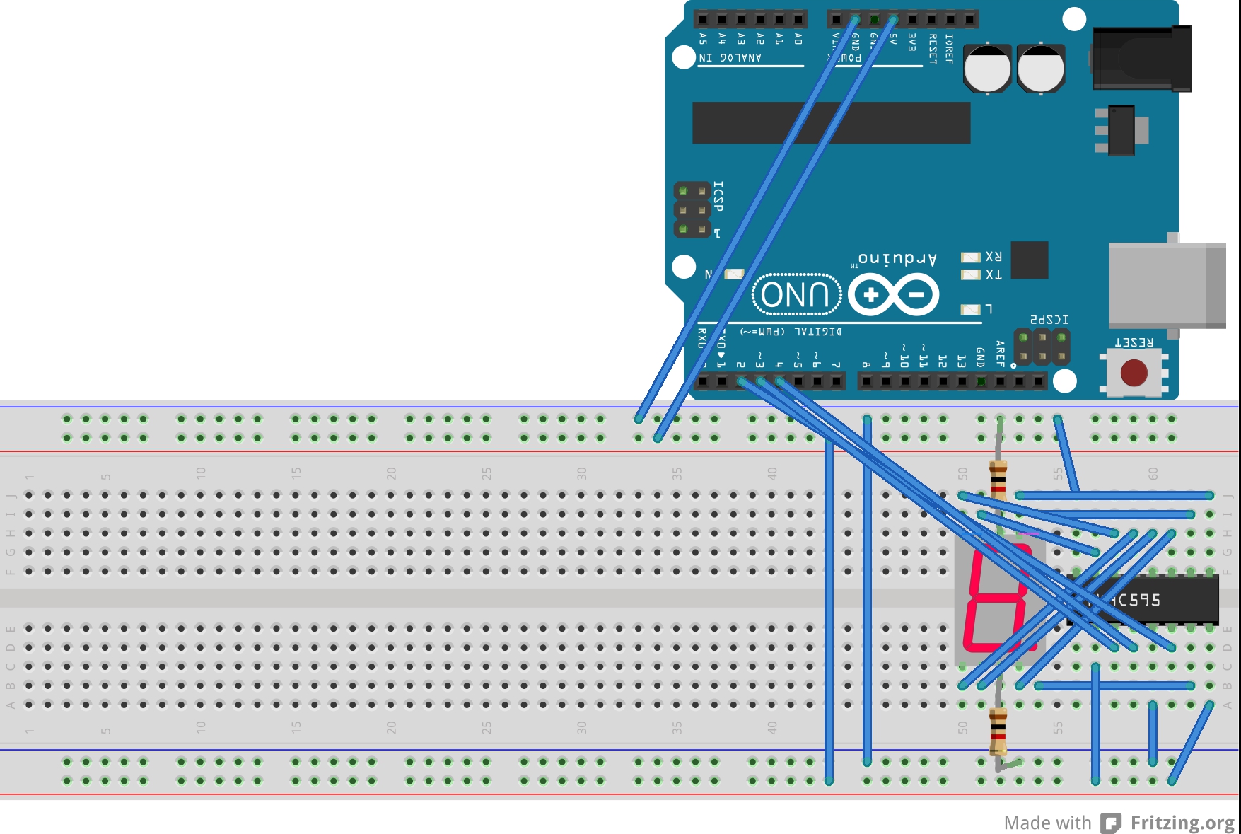
Next up was using the 7-segment display and the shift register. After a lot of googling and experimenting – finally managed to set it up so that it counts from 0 to 9. I used the on-board switch on pin # 7. Had to use a lot of binary to decimal conversions to get the numbers correct – but finally got it down pat 🙂

Attached circuit diagram and sketch if anyone’s interested.

7-segment_bb

//Pin connected to ST_CP of 74HC595
int latchPin = 4;
//Pin connected to SH_CP of 74HC595
int clockPin = 3;
////Pin connected to DS of 74HC595
int dataPin = 2;
int buttonPin = 7;
int numberToDisplay = 0;
int segNumbers[10] = {126,48,109,121,51,91,95,112,127,123};

void setup() {
  //set pins to output so you can control the shift register
  pinMode(latchPin, OUTPUT);
  pinMode(clockPin, OUTPUT);
  pinMode(dataPin, OUTPUT);
  pinMode(buttonPin,INPUT_PULLUP);
}

void loop() {
      // take the latchPin low so 
      // the LEDs don't change while you're sending in bits:
      digitalWrite(latchPin, LOW);
      // shift out the bits:
      shiftOut(dataPin, clockPin, LSBFIRST, segNumbers[numberToDisplay]);  
      //take the latch pin high so the LEDs will light up:
      digitalWrite(latchPin, HIGH);
      if (digitalRead(buttonPin) == LOW){
        numberToDisplay++;
        if (numberToDisplay > 9) {numberToDisplay = 0;}
      }
      while(digitalRead(buttonPin)==0);
      delay(100);
}

My start in the electronics world

Have always been fascinated with electronics and computers – but never knew how to go about it.

Finally got a chance to experiment – when Abhiram decided to hold a small electronics workshop. Well – got up early (comparatively) on a Saturday and went to see what could happen.

Workshop


The workshop was great – Abhiram started right from the basics of analog circuits and went on to explain how digital circuits are created using microcontrollers. In addition to all this – he arranged for starter kits for us – which included an Induino and lots of LEDs, resistors, sensors, et al to get us started. (Though he did warn us that this was an expensive hobby :-))

Anyways – long story short – I had a lot of fun and am now hooked to microcontroller programming.