20. April 2014
LED Clock
One of my clocks stopped working – and it happened to be a clock my wife likes a lot. Went to the repair shop and the guy said that he didn’t have the spare parts and could not repair this. So – I thought – why not build an LED clock – I had tons of LEDs and an RTC module just waiting to be used.
The original plan was to make a charlieplexed LED clock – 60 LEDs working off 9 pins and 12 LEDs working off 4 pins – so doable with a standalone arduino. This was to be powered off 4 AA cells.
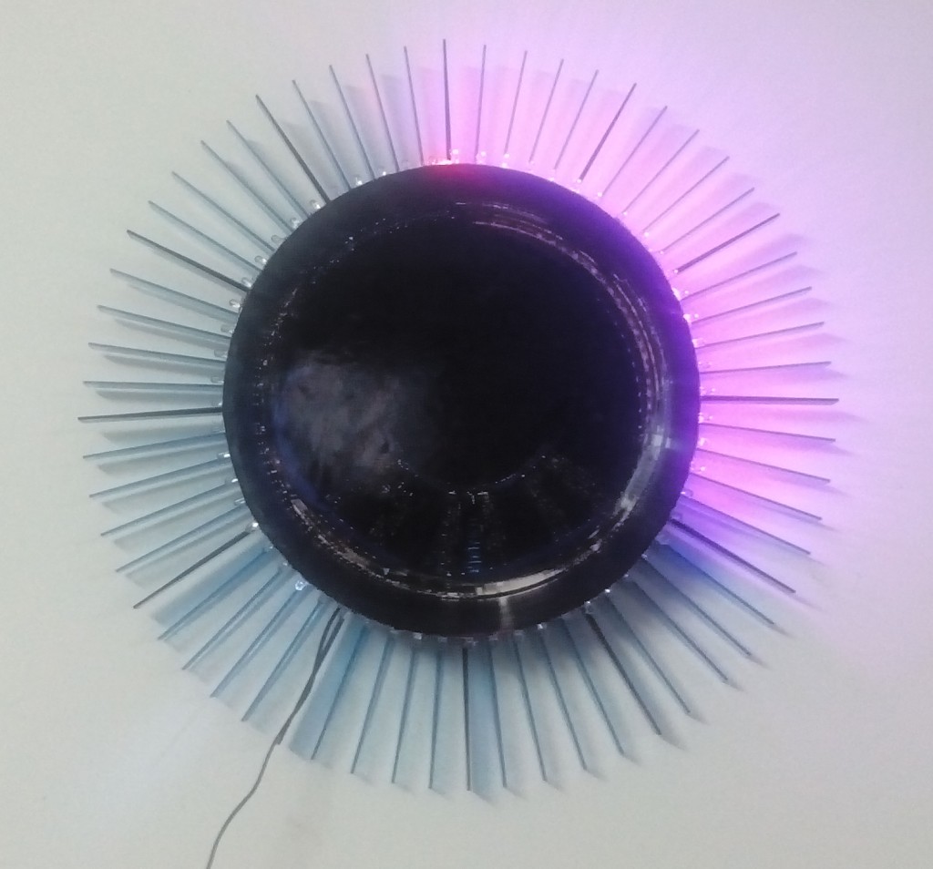
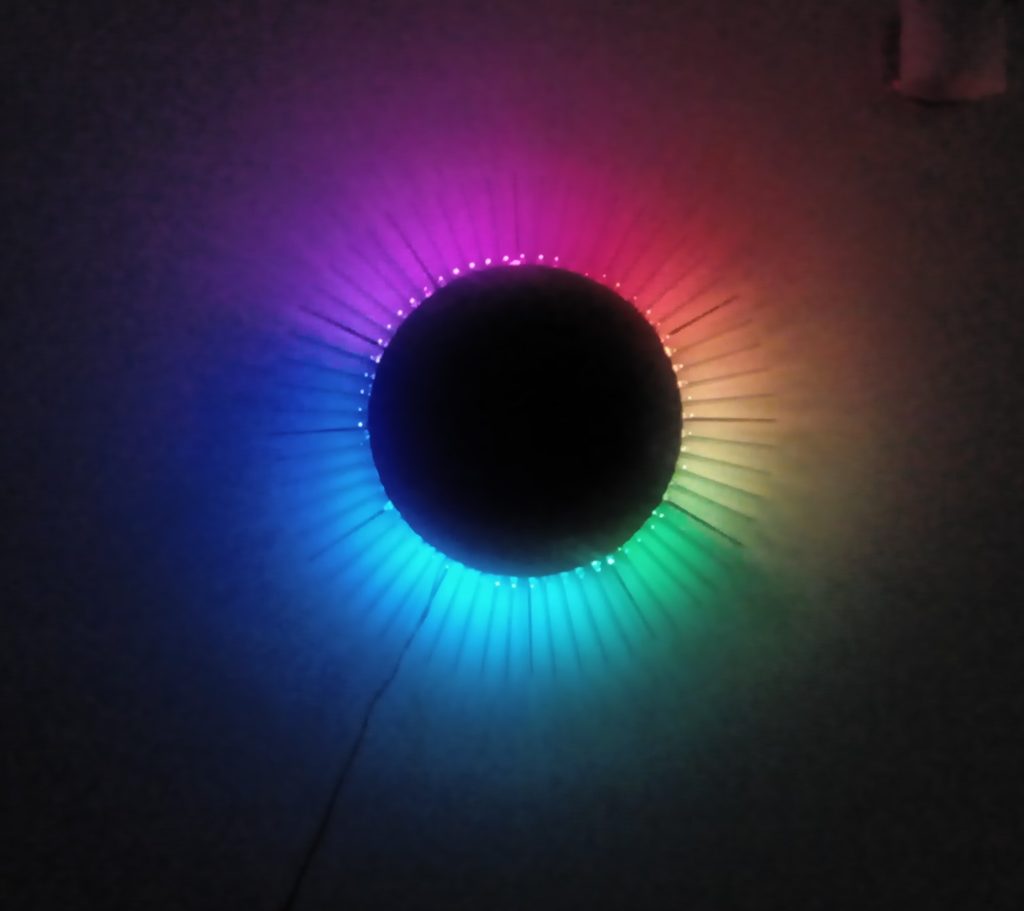
However, before the clock was finished – a couple of rolls of WS2812B RGB LED strips came – I had ordered these a couple of months ago – and they came at the perfect time. When my wife saw the effects that could be generated using these, there was no going back. Now, we had spent considerable amount of time sticking the charlie-plexed LEDs and soldering them – so I was unwilling to give them up. Finally, we used the white LEDs to show seconds, and a strip of 60 RGB LEDs for the minutes and hours. Currently the code runs a rainbow every minute, shows a RED dot for hours and colours all the LEDs from 0 to the minute purple. It was a pain creating this, but the end result is amazing.
Hardware
- A standalone arduino
- 60 White LEDs – 5mm
- 9 resistors – 110 ?
- WS2812B RGB LED strip – 60 LEDs
- RTC Module – DS1307
- Some headers, wires, etc
- 12V – 800mA adapter
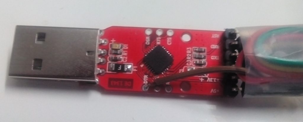
- CP2102 USB-to-TTL (the RST pin on the CP2102 is not for resetting the arduino – you have to solder a wire to the DTR pad on the PCB – which sends a reset signal to program the arduino. This has to be connected to the reset pin through a 104 capacitor) or Arduino to program the standalone processor as discussed in the previous post.
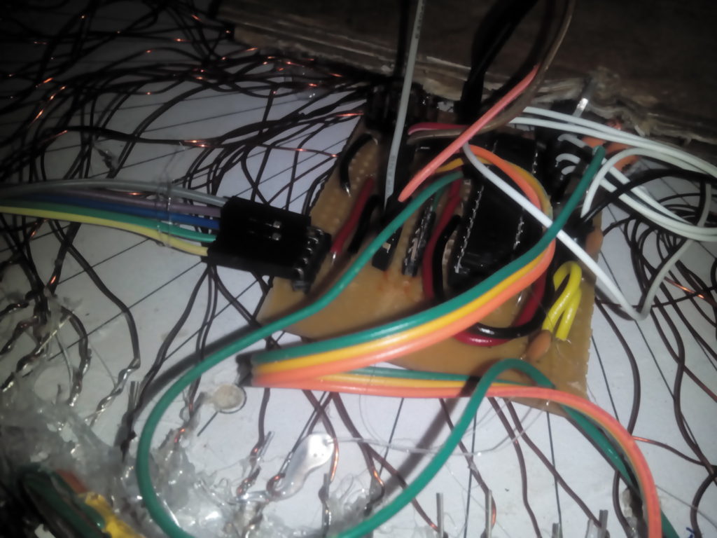
The standalone arduino board:
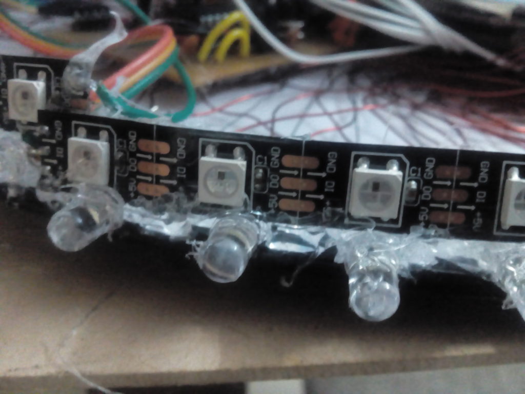
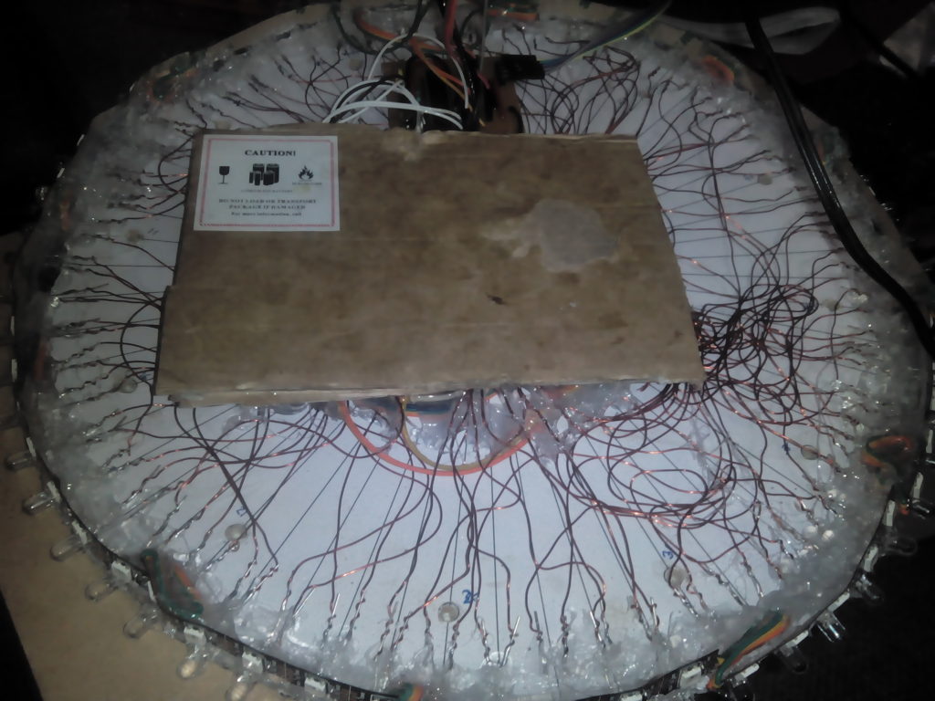
 The white LEDs and the RGB LED strip:
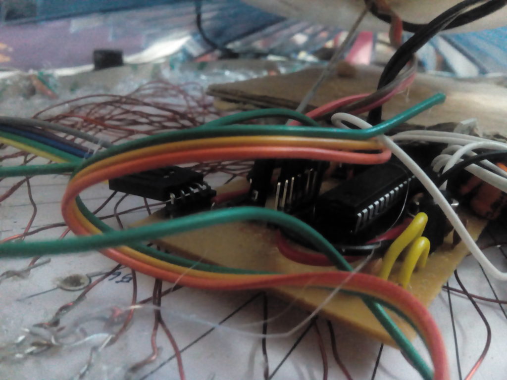
The CP2102 USB-to-TTL converter (note the connection to the DTR pad):
The Circuit
Prepared the following plan to solder the charlie-plexed LEDs using a stripboard: !
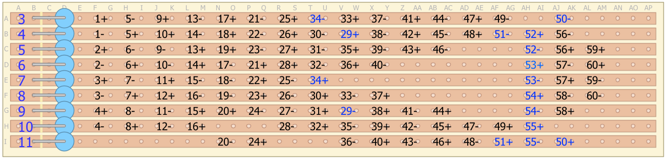
The blue numbers in the above diagram are due to errors while soldering (and what a pain it was…).
 The rest of the circuit is simple:
- Pins 1-11 of the arduino to the above circuit
- Pin 12 to data pin of the LED strip
- SDA and SCL pins to the RTC module’s SDA and SCL pins.
The Code
#include "Wire.h"
#include "RTClib.h"
#include "FastLED.h"

byte LEDs[][2]={ // Array to define the Charlieplexed LEDs
  {3,4},
  {5,6},
  {7,8},
  {9,10},
  {4,3},    // 5
  {6,5},
  {8,7},
  {10,9},
  {3,5},
  {4,6},    //10
  {7,9},
  {8,10},
  {5,3},
  {6,4},
  {9,7},    //15
  {10,8},
  {3,6},
  {4,7},
  {5,8},
  {9,11},    //20
  {6,3},
  {7,4},
  {8,5},
  {11,9},
  {3,7},    //25
  {4,8},
  {5,9},
  {6,10},
  {4,9},
  {8,4},    //30
  {9,5},
  {10,6},
  {3,8},
  {7,3},
  {5,10},    //35
  {6,11},
  {8,3},
  {9,4},
  {10,5},
  {11,6},    //40
  {3,9},
  {4,10},
  {5,11},
  {9,3},
  {10,4},    //45
  {11,5},
  {3,10},
  {4,11},
  {10,3},
  {11,3},    //50
  {11,4},
  {4,5},
  {6,7},
  {8,9},
  {10,11},  //55
  {5,4},
  {7,6},
  {9,8},
  {5,7},
  {6,8}      //60
};

#define NUM_LEDS 60
#define DATA_PIN 12
CRGB leds[NUM_LEDS];
byte lastmin;
RTC_DS1307 rtc;

void setup() {
  // put your setup code here, to run once:
  AllOff();
#ifdef AVR
  Wire.begin();
#else
  Wire1.begin(); // Shield I2C pins connect to alt I2C bus on Arduino Due
#endif
  rtc.begin();
  lastmin=0;
  LEDS.setBrightness(128);
  FastLED.addLeds<WS2812B, DATA_PIN, GRB>(leds, NUM_LEDS);
  //effects();
  //Serial.begin(57600);
}

void loop() {
  // put your main code here, to run repeatedly:
  DateTime now = rtc.now();
  // Serial.print(now.hour(), DEC);
  if(( now.second() == 0)){
    effects();
  }
  if(now.minute() != lastmin){
    for(int i=0; i<now.minute();i++)
      leds[i] = CRGB::Purple;
    leds[((now.hour())%12)*5] = CRGB::Red;
    FastLED.show();
  }
  LEDOn(now.second());
  delay(900);
  AllOff();
  //leds[((now.hour())%12)*5] = CRGB::Black;
  //leds[now.minute()] = CRGB::Black;
  //FastLED.show();
  delay(100);
  //}
}

void LEDOn(byte n){
  AllOff();
  pinMode(LEDs[n][0],OUTPUT);
  pinMode(LEDs[n][1],OUTPUT);
  digitalWrite(LEDs[n][0],HIGH);
  digitalWrite(LEDs[n][1],LOW);
}

void AllOff(){
  for(int i=3;i<=11;i++){
    pinMode(i,INPUT);
  }
}

const int colorWheelAngle = 360 / NUM_LEDS;

void effects(){
    uint8_t color[3];
  for (int i = 0; i < 360; i++) {
    for (int j = 0; j < NUM_LEDS; j++) {
      getRGB((i + (j * colorWheelAngle)) % 360, 255, 150, color);
      leds[j]=CRGB(color[0], color[1], color[2]);
    }
    FastLED.show();
    delay(1);
  }
  for (int i = 0; i < NUM_LEDS; i++) {
     leds[i] = CRGB::Black;
  }
  FastLED.show();
}

// Gamma values used to convert HSV to RGB
PROGMEM const byte dim_curve[] = {
 0, 1, 1, 2, 2, 2, 2, 2, 2, 3, 3, 3, 3, 3, 3, 3,
 3, 3, 3, 3, 3, 3, 3, 4, 4, 4, 4, 4, 4, 4, 4, 4,
 4, 4, 4, 5, 5, 5, 5, 5, 5, 5, 5, 5, 5, 6, 6, 6,
 6, 6, 6, 6, 6, 7, 7, 7, 7, 7, 7, 7, 8, 8, 8, 8,
 8, 8, 9, 9, 9, 9, 9, 9, 10, 10, 10, 10, 10, 11, 11, 11,
 11, 11, 12, 12, 12, 12, 12, 13, 13, 13, 13, 14, 14, 14, 14, 15,
 15, 15, 16, 16, 16, 16, 17, 17, 17, 18, 18, 18, 19, 19, 19, 20,
 20, 20, 21, 21, 22, 22, 22, 23, 23, 24, 24, 25, 25, 25, 26, 26,
 27, 27, 28, 28, 29, 29, 30, 30, 31, 32, 32, 33, 33, 34, 35, 35,
 36, 36, 37, 38, 38, 39, 40, 40, 41, 42, 43, 43, 44, 45, 46, 47,
 48, 48, 49, 50, 51, 52, 53, 54, 55, 56, 57, 58, 59, 60, 61, 62,
 63, 64, 65, 66, 68, 69, 70, 71, 73, 74, 75, 76, 78, 79, 81, 82,
 83, 85, 86, 88, 90, 91, 93, 94, 96, 98, 99, 101, 103, 105, 107, 109,
 110, 112, 114, 116, 118, 121, 123, 125, 127, 129, 132, 134, 136, 139, 141, 144,
 146, 149, 151, 154, 157, 159, 162, 165, 168, 171, 174, 177, 180, 183, 186, 190,
 193, 196, 200, 203, 207, 211, 214, 218, 222, 226, 230, 234, 238, 242, 248, 255,
};


/*
 * Code taken from http://www.kasperkamperman.com/blog/arduino/arduino-programming-hsb-to-rgb/
 * hue ranges from 0 to 360
 * sat is from 0 to 255
 * val is from 0 to 255
 */
void getRGB(int hue, uint8_t sat, uint8_t val, uint8_t colors[3]) {
 /* convert hue, saturation and brightness ( HSB/HSV ) to RGB
 The dim_curve is used only on brightness/value and on saturation (inverted).
 This looks the most natural.
 */

 val = pgm_read_byte(&dim_curve[val]);
 sat = 255 - pgm_read_byte(dim_curve[255-sat]);

 int r;
 int g;
 int b;
 int base;

 if (sat == 0) { // Acromatic color (gray). Hue doesn't mind.
 colors[0]=val;
 colors[1]=val;
 colors[2]=val;
 } else {

 base = ((255 - sat) * val)>>8;
    switch(hue/60) {
    case 0:
        r = val;
        g = (((val-base)*hue)/60)+base;
        b = base;
    break;

    case 1:
        r = (((val-base)*(60-(hue%60)))/60)+base;
        g = val;
        b = base;
    break;

    case 2:
        r = base;
        g = val;
        b = (((val-base)*(hue%60))/60)+base;
    break;

    case 3:
        r = base;
        g = (((val-base)*(60-(hue%60)))/60)+base;
        b = val;
    break;

    case 4:
        r = (((val-base)*(hue%60))/60)+base;
        g = base;
        b = val;
    break;

    case 5:
        r = val;
        g = base;
        b = (((val-base)*(60-(hue%60)))/60)+base;
    break;
    }

    colors[0]=(uint8_t) r;
    colors[1]=(uint8_t) g;
    colors[2]=(uint8_t) b;
  }
}
Clock Face
For the clock-face I pulled out one of my photographs from Singapore and modified it to suit a clock face.
Original: 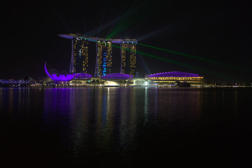 Clock Face:
 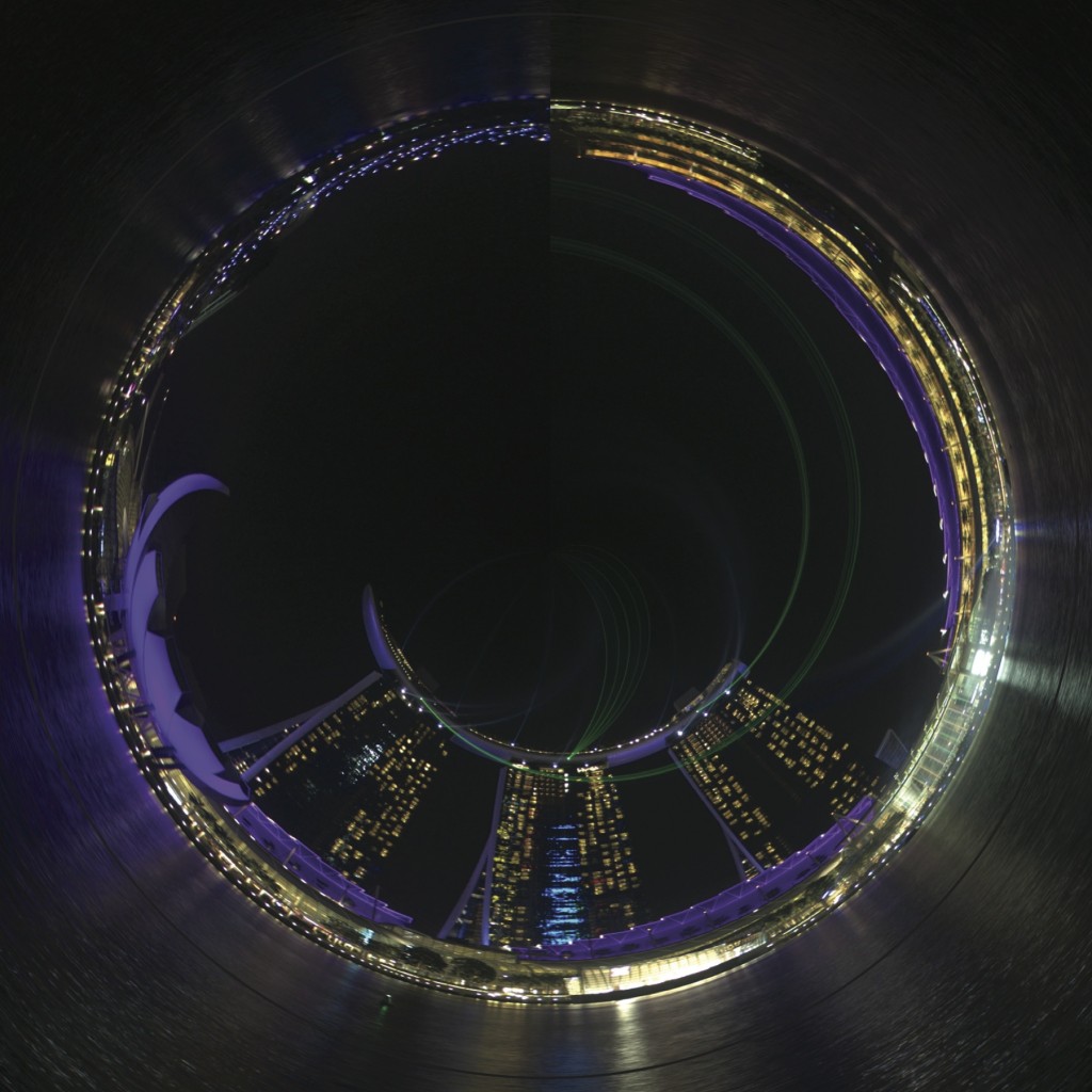 Stuck it to the original clock and voila…
Final Result

To Do
- Incorporate an LDR to dim the LEDs at night, when the lights are off
- Setup a wireless controller so that I can switch off /dim the LEDs when I want
- Incorporate a PIR sensor to give basic gesture controls
Lessons Learnt
- Do not use charlie-plexing – its a pain to solder all the LEDs correctly and get the code right – its easier to use shift registers.
- Do not use the thin copper wires with resin insulation – I had assumed that I could burn off the resin using my soldering iron; however I had to strip off the insulation manually using a sandpaper – huge pain
- Use a larger stripboard and – to ensure there is space between the rows of charlie-plexed connections. I ended up with three boards instead of one as I made mistakes while soldering and it was difficult to troubleshoot. I could have soldered the entire thing in half the time had I used a larger stripboard and kept space between adjacent rows.
As usual – comments welcome.