
17
Mar
2014
Cubetto Clone
|
Category: Electronics
Based on an idea from http://primo.io, I set about making one for my son. Loosely based on their schematics, I have made the following:
Hardware:
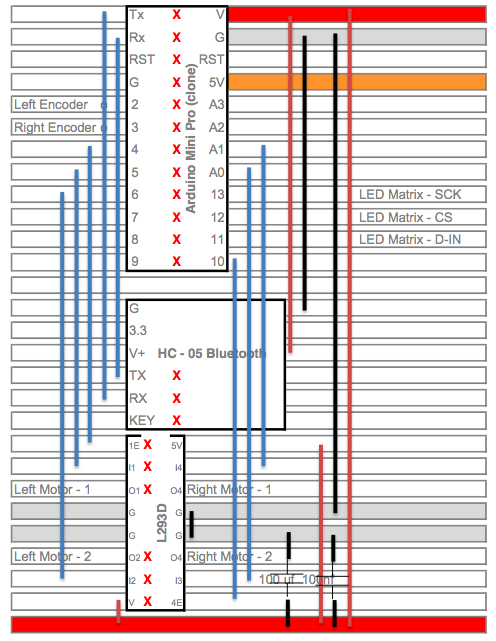
- Funduino Mini Pro – I don’t think it makes sense to use a full arduino for such a small project
- Bluetooth Breakout (HC-05) Board – The cubetto proposes a XBee module – I prefer bluetooth as it allows me to control the robot using a mobile / tablet / etc.
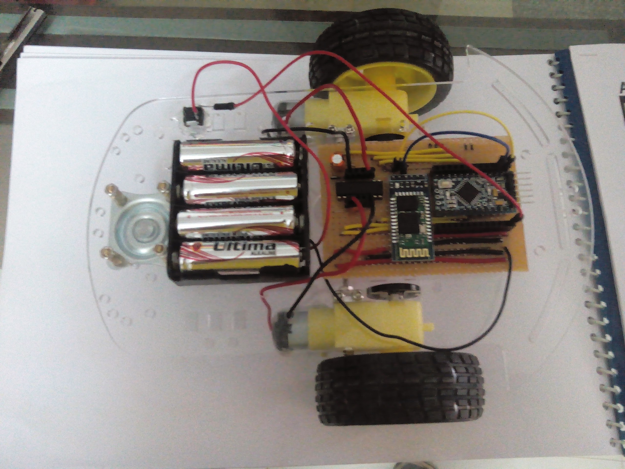
- Robot Car Chassis – This was just easier to implement as the chassis is readymade and cheap
- L293D Motor Driver
- MOC7811 Encoder Sensor – This sensor fit perfectly in the chassis as it included a plastic encoder.
Soldered it on a stripboard:

I soldered some female headers so that I can add to the circuit – specifically add more sensors / LED matrix without having to re-solder.
Software:
#include <SerialCommand.h>

#define ENABLE_LEFT 4
#define LEFT_1 5
#define LEFT_2 6
#define ENABLE_RIGHT 10
#define RIGHT_1 A1
#define RIGHT_2 A0

// Not used right now - for future use
#define SCK_PIN 13              // for Max7221 powered LED Matrix
#define CS_PIN  12
#define DIN_PIN 11
#define LEFT_ENCODER 2      // For speed encoders
#define RIGHT_ENCODER 3

SerialCommand sCmd;

void setup() {
  // put your setup code here, to run once:
  pinMode(ENABLE_LEFT, OUTPUT);
  pinMode(LEFT_1, OUTPUT);
  pinMode(LEFT_2, OUTPUT);
  pinMode(ENABLE_RIGHT, OUTPUT);
  pinMode(RIGHT_1, OUTPUT);
  pinMode(RIGHT_2, OUTPUT);
  digitalWrite(ENABLE_LEFT, HIGH);
  digitalWrite(ENABLE_RIGHT,HIGH);
  stop();
  Serial.begin(9600);
  sCmd.addCommand("F", forward);
  sCmd.addCommand("R", right);
  sCmd.addCommand("L", left);
  sCmd.addCommand("B", back);
}

void loop() {
  // put your main code here, to run repeatedly:
  sCmd.readSerial();
  Serial.println("TEST");
  delay(1000);
}

void forward(){
  Serial.println("Forward");
  digitalWrite(LEFT_1, HIGH);
  digitalWrite(RIGHT_1,HIGH);
  delay(1000);
  stop();
}

void right(){
  Serial.println("Right");
  digitalWrite(RIGHT_1,HIGH);
  delay(600);
  stop();
}

void left(){
  Serial.println("Left");
  digitalWrite(LEFT_1,HIGH);
  delay(600);
  stop();
}

void back(){
  Serial.println("Back");
  digitalWrite(LEFT_2, HIGH);
  digitalWrite(RIGHT_2,HIGH);
  delay(1000);
  stop();
}

void stop(){
  digitalWrite(LEFT_1, LOW);
  digitalWrite(RIGHT_1,LOW);
  digitalWrite(LEFT_2, LOW);
  digitalWrite(RIGHT_2,LOW);
}
This works with Bluetooth SPP Pro.
To Do:
- Wooden / Acrylic case like the cubetto
- Enhance the software to use the encoders (I’m thinking of using the hardware interrupts – but let’s see)
- The Primo interface board
- Add an LED matrix – I have already built a breakout using an 8×8 LED matrix and a MAX7221 – will connect this to the arduino
- Add some LEDs – just for fun 🙂
Suggestions welcome…